If you're commissioning a topographical survey, one of the most common deliverables requested is an AutoCAD DWG file.
Architects, engineers and planning consultants rely on these drawings to design buildings, prepare planning applications and produce technical construction drawings.
But not all AutoCAD survey files are created equal.
In practice, many designers receive DWG files that are difficult to use, poorly layered, incorrectly scaled, or even exported from PDFs rather than generated from real survey data.
Understanding what a proper topographical survey AutoCAD file should contain can save days of redesign work and prevent planning submission delays.
This guide explains:
-
How AutoCAD survey files are structured
-
The most common mistakes in survey drawings
-
How survey data is used in planning and design
What Is a Topographical Survey in AutoCAD?
A topographical survey AutoCAD file is a digital drawing of surveyed site data delivered in DWG or DXF format.
It represents real-world features measured on site using total stations, GPS, or laser scanning equipment.
Typical features shown include:
-
Building footprints
-
Site boundaries
-
Ground levels
-
Contours
-
Trees and vegetation
-
Utilities covers
-
Kerbs and road edges
-
Walls and fences
Instead of a static PDF drawing, a DWG file allows designers to:
-
Edit linework
-
Measure distances
-
Extract levels
-
Build 3D models
-
Insert architectural designs
This makes the AutoCAD format essential for design workflows and planning drawings.
What a Proper AutoCAD Topographical Survey Should Contain
A professional survey DWG should include structured information that allows designers to work efficiently.
1. Correct Coordinate System
Survey drawings should normally be referenced to the British National Grid (OSGB36).
This ensures:
-
alignment with Ordnance Survey mapping
-
compatibility with location plans
-
accurate positioning in GIS systems
If a survey uses an arbitrary coordinate system, architects may struggle to overlay:
-
location plans
-
aerial imagery
This can cause serious alignment errors later in the design process.
2. Structured Layering
AutoCAD surveys should separate features into logical layers.
Typical survey layers include:
-
buildings
-
boundaries
-
contours
-
spot levels
-
trees
-
utilities
-
road features
Proper layering allows designers to:
-
isolate elements quickly
-
hide unnecessary detail
-
generate specific drawings such as site plans or drainage layouts
Poorly layered drawings are one of the biggest frustrations for architects.
3. Spot Levels and Contours
Ground levels are one of the most important parts of a topographical survey.
AutoCAD surveys usually include:
-
spot levels (measured points)
-
contours (lines connecting equal heights)
Typical contour intervals include:
-
0.25m for detailed design
-
0.5m for residential sites
-
1m for large land parcels
Using contours that are too wide can make slope design and drainage calculations inaccurate.
4. Tree Survey Data
Trees are often recorded during topographical surveys.
A DWG file may include:
-
tree position
-
canopy spread
-
trunk diameter
-
tree reference numbers
This information is crucial for:
-
arboricultural reports
-
planning constraints
-
tree protection zones
Incorrect tree locations can lead to planning complications.
5. Boundary Information
Site boundaries should be clearly represented within the survey.
However, it's important to understand:
A topographical survey does not legally define property boundaries.
Instead it typically shows:
-
fences
-
walls
-
hedge lines
-
boundary markers
Legal boundaries require separate title investigation or boundary surveys.
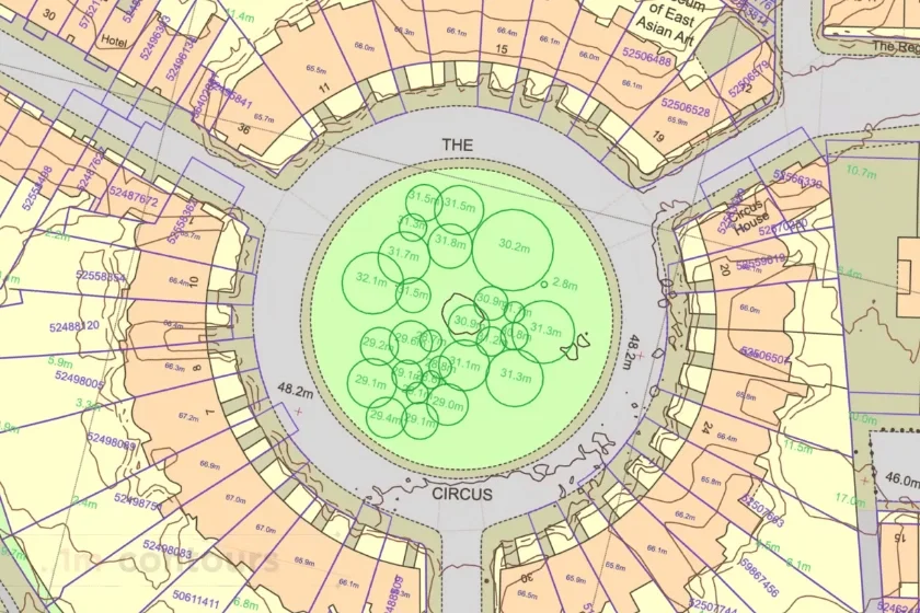
Example of a MasterMap® sample with additional layers including 1m contours, freehold boundaries, the National Tree Map and building heights. Provided by MapServe
How AutoCAD Survey Files Are Used in Planning Applications
Most planning drawings are built directly on top of survey data.
For example:
Site Plans
Architects place proposed buildings directly onto the survey base drawing.
This ensures:
-
correct distances to boundaries
-
accurate building orientation
-
realistic site levels
Drainage Design
Ground levels from the survey are used to design:
-
surface water drainage
-
foul drainage
-
attenuation systems
Without accurate survey levels, drainage design becomes unreliable.
Building Height Calculations
Survey levels determine:
-
finished floor levels
-
ridge heights
-
step changes in terrain
These values are often required in planning documents.
Common Problems With AutoCAD Survey Files
Even when a survey is delivered as a DWG file, it may still cause design issues.
Flattened Drawings
Some survey providers export drawings from PDFs.
This creates DWG files where:
-
contours are broken
-
text becomes exploded geometry
-
levels are not properly structured
Designers often need to redraw these elements.
Incorrect Scaling
Survey drawings should normally be drawn 1:1 in AutoCAD model space.
If scaling is incorrect, designers may find that:
-
dimensions are wrong
-
buildings do not align
-
measurements become unreliable
Missing Levels
Some surveys include contours but lack enough spot levels.
This makes it difficult to:
-
understand subtle slopes
-
design drainage
-
calculate cut and fill volumes
Poor Layer Naming
Survey layers should follow logical naming conventions.
For example:
-
SURV_CONTOURS
-
SURV_SPOT_LEVELS
-
SURV_BUILDINGS
Without proper naming, designers waste time locating the correct data.
DWG vs DXF Survey Files
Survey drawings are typically delivered in:
DWG
The native AutoCAD file format.
DXF
A compatible exchange format for other CAD software.
Most architects prefer DWG files because they maintain:
-
better object properties
-
cleaner layering
-
higher editing compatibility.
How to Request a Topographical Survey AutoCAD File
When commissioning a survey, it helps to specify exactly what you need.
A typical specification may include:
-
AutoCAD DWG format
-
British National Grid coordinates
-
contours at required intervals
-
spot levels across the site
-
tree positions and attributes
-
building outlines
-
utilities covers
-
kerb lines and road features
Providing this specification reduces the chance of receiving unusable drawings.
When a Topographical Survey Is Required
AutoCAD surveys are commonly needed for:
-
planning applications
-
architectural design
-
site feasibility studies
-
drainage design
-
landscape architecture
-
redevelopment projects
Even relatively small projects benefit from a reliable survey base drawing.
Getting Survey Data Ready for Design
A good survey should integrate smoothly with your design software.
Architects should be able to:
-
insert the DWG into AutoCAD or Revit
-
reference OS mapping
-
begin designing immediately
If your survey requires significant cleaning or rebuilding, it likely wasn't structured properly from the start.
Ordering a Professional Topographical Survey
If you're preparing a planning application or starting site design, obtaining a properly structured AutoCAD survey drawing is essential.
Professional survey data ensures:
-
accurate design drawings
-
fewer redesign cycles
-
smoother planning submissions.
You can order a professionally prepared survey through MapServe®, delivered in AutoCAD-ready format for architects and designers.
FAQs
What format is a topographical survey delivered in?
Most surveys are delivered as AutoCAD DWG files, often with accompanying PDFs and DXF versions.
Are AutoCAD surveys required for planning applications?
While planning drawings are usually submitted as PDFs, architects normally design them using AutoCAD survey data.
What contour interval should a topographical survey use?
Residential sites commonly use 0.5m contours, while more detailed designs may require 0.25m intervals.
Does a topographical survey show legal boundaries?
No. Surveys show physical boundary features such as fences or walls, not legal title boundaries.
Can architects edit topographical survey DWG files?
Yes. AutoCAD survey drawings are designed to be editable so architects can build design proposals on top of them.